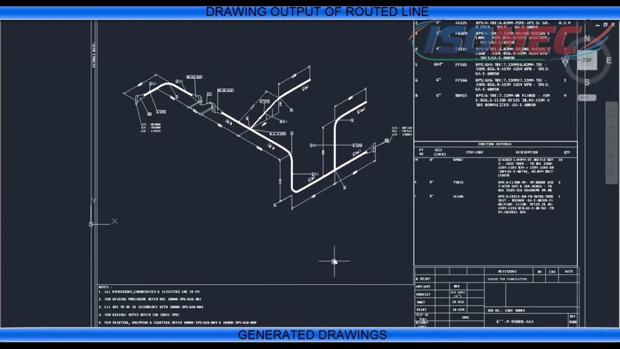
To provide detail about the components, a 5 letter system is used: They are a standard set of symbols used for the identification of measurements and functionality within the process. PFDs use specific shapes to represent different equipment, valves, instruments, and piping flow in a system. Once you familiarise yourself with these features, you’ll be able to trace the lines in a system to understand specific components and the overall function in the case of PFDs and P&IDs or understand the manufacture and assembly of a product in the context of mechanical engineering. To read an ED, you must first become familiar with the various symbols, abbreviations, and diagram basics. Engineering Drawing Abbreviations and Symbols They are far less detailed and shows the system overall.

PFDs differ from P&IDs, showing a more general overview of a system. To find out how to draw P&ID, click here, and to understand how to mark up a drawing in real-time, click here. Permanent start-up, finish and bypass lines.Specific piping data can be read from a diagram, including: Process piping sizes and identification.


 0 kommentar(er)
